The turbo-molecular pump extraction system with separate roughing lines shown in Figure 1 operates in a similar manner to the diffusion pump extraction system. Before starting rough pumping, the high vacuum valve and roughing valve are closed while the foreline valve is open. First, close the front-stage valve, start roughing pump (also front-stage pump), open roughing valve to start vacuuming the vacuum chamber. Turn off the roughing valve when the pressure in the vacuum chamber drops to 150 ~ 100Pa, open the foreline valve, and then start the turbo molecular pump (need to connect the cooling system first). If the inlet of the molecular pump is filled with liquid nitrogen cold trap, liquid nitrogen should be filled after the pump is accelerated to rated speed (usually 5 ~ 10min).
Figure 1 Typical turbomolecular pumping system
1. Turbomolecular pump 2. Liquid nitrogen cold trap 3. Bleed valve 4. Ionization gauge 5. Heat conduction gauge 6. Roughing valve 7. Mechanical pump 8. Foreline pipe valve 9. High vacuum valve coarse pumping system configuration With the volume of the vacuum chamber and the size of different. For 500L / s or smaller turbo molecular pump, a two-stage rotary vane pump can be used; while the turbopumps with a capacity of 1000L / s and more adopt the mechanical pump as the primary pump's Roots pump unit. Close the roughing valve at a pressure of 100 to 150 Pa and switch the vacuum chamber to the turbomolecular pump. For some pumps, doing so causes a slight, but slow, instantaneous deceleration, but this has no effect on pumping. Just as the diffusion pump extraction system, the most important substance in the turbomolecular pump system is water vapor, and its pumping time will be governed by the liquid nitrogen trap pumping speed. Without a liquid nitrogen cold trap, the system will pump water slightly slower than a cold-trap diffusion pump of the same pumping speed. At the very beginning of a high-vacuum pumping process, the pump's large, unbaked interior surface will adsorb water and then be released again at a lower pressure. This effect is more pronounced in valveless systems because it may adsorb more water vapor than a valved system that is not exposed to air at pressures higher than 150 Pa.
When the system is shut down, close the high vacuum valve first, and if there is a liquid nitrogen cold trap, heat the trap. After the cold trap reaches the equilibrium temperature, turn off the foreline valve, and then cut off the power supply of the turbopump motor to decelerate the molecular pump rotor. In general, it takes ten minutes or more until the pump rotor stops completely. During the deceleration of the molecular pump rotor, the hydrocarbon vapors from the foreline hydrocarbons and turbomolecular pumps rapidly diffuse to the area above the pump inlet. To prevent backflow of the mechanical pump vapor and turbo molecular pump lubricant vapors, the molecular pump is deflated with a dry reverse flow of air after the power to the turbo pump motor has been switched off. For example, when the pump rotor speed drops to about 50% of the maximum speed, argon or nitrogen should be continuously charged somewhere above the pump inlet or above the rotor assembly until the pressure in the pump reaches atmospheric pressure. This can be done properly by filling the valve 3 (see Figure 1) with gas. Turbomolecular pumps should not be filled with air at atmospheric pressure often when operating at rated speed. This is detrimental to the life of the shaft. After the current level pipeline valve is closed, the mechanical pump system can be switched off, and the deflation valve can be used to deflate the mechanical pump. Turn off the cooling water immediately after shutdown to prevent internal condensation. In normal operation, the water temperature can be adjusted slightly above the dew point to eliminate possible condensate outside the pump body. Start the system to connect the cooling water flow, open the foreline valve, and then start the mechanical pump and turbo molecular pump. After the pump is accelerated to the rated speed (typically 5 to 10 minutes), the liquid nitrogen cold trap can be filled. The vacuum chamber can then be evacuated as described in the previous section. The extraction system shown in Figure 2 without the use of high vacuum valves is much easier to operate than a valved extraction system. Operation, first open the cooling water and the foreline valve, and at the same time start the mechanical pump and turbo molecular pump. If the roughing pump is properly chosen so that the roughing time of the vacuum chamber is equal to the acceleration time, the vacuum system can pump the vacuum chamber to its background pressure without the return of the pump oil vapor.
Figure 2 Turbomolecular pumping without valve system
1. Leakage interface valve 2. Turbomolecular pump 3. Bleed valve 4. Ionization gauge 5. Heat conduction gauge 6. Vacuum line valve 7. Electromagnetic bleed valve 8. Mechanical pump valveless system During deflation and shutdown, first Close the foreline valve, and wait for the pump speed to drop to 50% of the maximum speed before charging dry gas above the pump. When the system is filled to atmospheric pressure should close the deflation valve, otherwise it will cause the vacuum chamber over-pressure. Then shut off the mechanical pump and stop the cooling water as described above. There is no turbo molecular pump system with a single roughing line: first turn on the molecular pump cooling system and foreline valves, and at the same time start the pre-stage (coarse pumping) mechanical pump and turbo-molecular pump. If the roughing pump (forepump) is properly selected so that the roughing time of the vacuum chamber equals the acceleration (start up) time of the molecular pump, the vacuum system can pump the vacuum chamber to it without the return flow of pump oil Background pressure.
Before shutting down the system, it is necessary to close the foreline valve, then cut off the power of the molecular pump and turn off the cooling water. When the molecular pump speed drops to half of the rated working speed, dry gas is filled in the pump inlet. When the system is filled to atmospheric pressure, the deflation valve should be closed. Shut off the forepump system at any time after the foreline valve is closed as needed.
Articles More Keywords: Pump
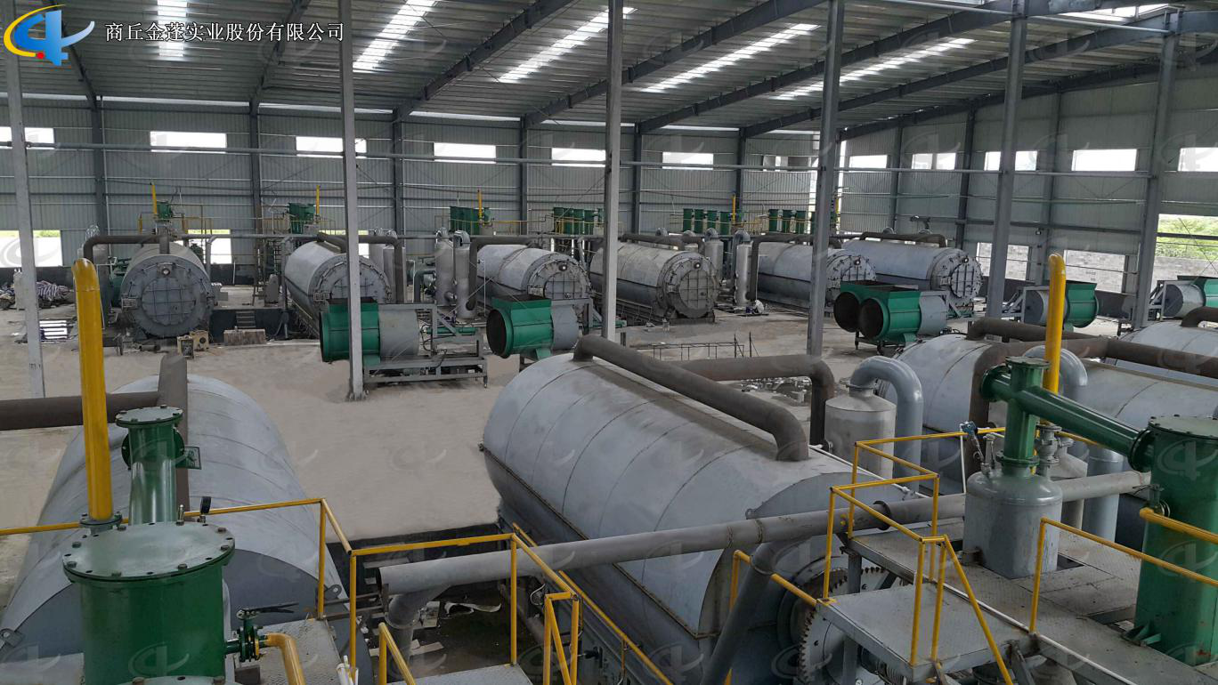
Semi-continuous Waste Tyre Pyrolysis Plant
Pyrolysis Plant is used for recycling waste tire, waste plastic, waste rubber to fuel oil. According to the actual situation in every country and district, we developed different models of Batch Pyrolysis Plants for waste tires, rubber and plastic with daily capacity 5 -10 tons.

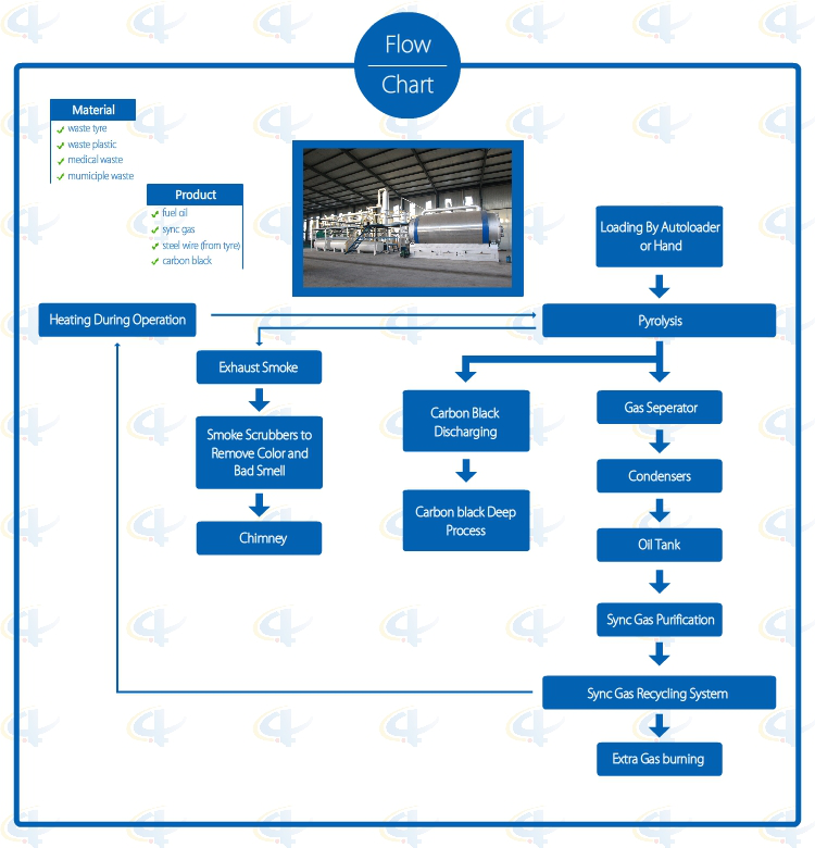
Flowchat of Batch Waste Tyre Pyrolysis Plant

Advantages of Batch Waste Tyre Pyrolysis Plant
1. Full open door design: Speedy loading in and steel pulling out; Easily cooling down after one batch finished, saving time; No leaking with special high temperature flexible graphite packing.
2. Unique Craft Condensers: High condensing efficiency with more oil output. Good quality oil, longer lifetime, and easy to clean.
3. National Patent Unique Smoke Scrubbers: More efficient removal of the acid gas and dust of the smoke by neutralization, purification and absorption, environmental friendly without pollution.
4. National Patent Carbon Black Discharging System: Speedy fully enclosed Auto-discharging under high temperature, avoiding carbon black pollution, saving time.
5. Automatic Submerged welding technology, ultrasonic nondestructive testing, both manual and the automatic safety devices.
6. Sync Gas Recycling System: Fully burned after recycling and utilization, saving fuel and preventing pollution.
7. Direct Heating System: Enlarging heating square to lengthen the lifespan of the reactor and easy to control the temperature.
8. National Patent, unique heat insulation shell; high efficiency temperature keeping, excellent energy-saving effect.
Technical Parameter of Batch Waste Tyre Pyrolysis Plant
|
NO. |
ITEM |
PROJECT |
|
|
1 |
Equipment Model |
XY-7 |
XY-8 |
|
2 |
Door Model |
Full Open Door |
Full Open Door |
|
3 |
Suitable Raw Materials |
Rubber/Plastic Products |
Rubber/Plastic Products |
|
4 |
Structure |
Horizontal Type Revolves |
Horizontal Type Revolves |
|
5 |
Reactor Size |
Φ2200*6000mm Φ2600*6600mm |
Φ2200*6000mm Φ2600*6600mm |
|
6 |
Capacity for One Batch |
5-6Mt; 8-10Mt |
5-6Mt; 8-10Mt |
|
7 |
Oil Yield of Tires |
40%-45% |
40%-45% |
|
8 |
Work Pressure |
Normal Pressure |
Normal Pressure |
|
9 |
Reactor Rotation Speed |
0.4R/M |
0.4R/M |
|
10 |
Fuels Choice |
Coal, Wood |
Coal, Wood, Gas, Oil |
|
11 |
Power |
18KW/H |
18-25KW/H |
|
12 |
Cooling Method |
Water Cycling |
Water Cycling |
|
13 |
Type of Drive |
External Annular Gear |
External Annular Gear |
|
14 |
Heating Method |
Direct |
Direct |
|
15 |
Type of Installation |
With Foundation |
With Foundation/Integrated Base |
|
16 |
Noise dB(A) |
≦85 |
≦85 |
|
17 |
Operation Mode |
Intermittent Operation |
Intermittent Operation |
|
18 |
Total Weight(MT) |
25-40 |
25-40 |
|
19 |
Installation Space Required |
30m*10m |
30m*10m |
|
20 |
Manpower |
3~4/batch |
3~4/batch |
|
21 |
Shipment |
Ф2200×6000=1*40HC+1*40FR Ф2600×6600=2*40HC+1*40FR |
Ф2200×6000=1*40HC+1*40FR Ф2600×6600=2*40HC+1*40FR |
Semi-Continuous Waste Tyre Pyrolysis Plant
Semi-Continuous Waste Tyre Pyrolysis Plant,Newest Semicontinuous Used Tyre Pyrolysis Plant,Semi-Continuous Rubber Pyrolysis Plant,Practical Semi-Continuous Waste Tyre Pyrolysis Plant
Shangqiu Jinpeng Industrial Co., Ltd. , https://www.recyclings.nl