1. INTRODUCTION In the metal cutting process, the chip shape is ever-changing. To realize the simulation of the chip formation process, the chip shape must be parameterized, and these parameter values ​​are calculated according to the processing conditions. Over the years, domestic and foreign scholars have conducted extensive in-depth studies on the shape and formation of chips, and established more than a dozen models of chip formation. Major achievements have been made in the direction of chip flow, the mechanism of chip curling, and the way in which chips are broken. However, due to the extremely complex chip problem, many studies are still qualitative, especially for the lateral curl of chips.
In this paper, according to the formation mechanism and deformation law of chip, the degree of primary and secondary factors affecting the chip shape are analyzed, and the mathematical model is established to realize the quantitative calculation of chip shape parameters and provide data for chip modeling.

Figure 1 Spiral chip shape parameters
2. Chip formation and shape parameters When the tool cuts into the workpiece, the cut metal layer undergoes plastic slip deformation through the shear plane to become chips, and then is curled and deformed by the cutter flute to form a spiral pitch chip with equal pitch. The shape of the spiral may be spiral. The diameter 2r, pitch p, and the angle q between the helicoidal surface and the axis are determined (Fig. 1). After the chips flow out, they are deformed or broken by obstacles such as workpieces, cutters, and machine tools, resulting in various types of chips. Therefore, other types of chips can be considered as the evolution and combination of spiral chips. According to the cutting mechanism, the parameters affecting the spiral cuttings are: 1/rx on the chip, 1/rz on the horizontal curl, and h on the chip. Then the shape parameters of the spiral chip can be expressed as

(1)

(2)

(3) There are many factors affecting 1/rx, 1/rz, and q in the cutting process, such as the nature of the material being processed, the amount of cutting, the geometry of the tool, coolant, and processing methods. Through the analysis and calculation of the main influencing factors and the comprehensive experiments on other factors, the quantitative calculation of the chip shape parameters can be achieved.

Figure 2 chip axis section parameters
3. Parameters of the chip axis section The parameters for determining the shape of the spiral chip section are: chip thickness hch, chip width bch, and chip offset kch (see Figure 2). According to the principle of cutting, the formula for calculating the axial section of the chip can be obtained: hch=Ahf sinkr (4) bch= ap sinkr (5)
Kch=arctan(Ahtankr) (6) The deformation coefficient Ah= cos(f-co) sinf where the feed amount f, the depth ap, the tool declination angle kr, and the rake angle co are known parameters, and the shear angle f Can be found using the experimental formula. 4. Calculation of chip curl rate

Figure 3 chip up curl
The swarf radius R0 is mainly related to the chip flute and built-up edge. Because the currently used carbide cutting tools have high cutting speeds, they generally do not generate built-up edge. Therefore, the effect of built-up edge on chip formation is not considered. When there is a chip flute on the knife surface, the chip flow is affected by the back wall of the flute, the chip is lifted, the root of the chip is affected by the bending moment, the compressive stress is formed on the free surface side, and the tensile stress is formed on the rake face side to make the chip An upward curl occurs (see Figure 3). This gives R0=(w-lf)cos(s/2)
The chip contact length lf=km hDsin(f+b-g0) sinfcosb cutting thickness hD=f·sinkr where w is the width of the chip flute, s is the angle at the bottom of the groove, the experimental coefficient is km≈2, and the friction angle b passes Cutting force can be found. Let Cx be the coefficient of integration of other influencing factors. The formula for calculating the curl rate on the chip is 1 = Cx = Cx rx R0 (w-lf)coss/2 (7) 5. Calculating the chip curl rate

Figure 4 chip lateral curl
At present, the research on the lateral curl of chips is only for qualitative analysis. There are two factors that affect the lateral curl of chips: the chips form lateral flow and secondary cutting edges in the width direction to participate in cutting. Based on this, the calculation formula of the chip lateral curvature is established theoretically, and the unknown factor is adjusted by the experimental coefficient. Let the deformation of the chip in the width direction be D, and the speed difference Dv=v2-v1 in the length direction caused by the obstacle of the workpiece, and the angular velocity w=v2/rz1=v1/(rz1-bD) (see Fig. 4). ); Let Dv = (D/kw1bD) v1, D = bch-bD, the coefficient kw1 is found by experiment, then the curvature caused by the side flow of the chip is 1 = D rz1 bD (D + kw1bD) In ​​the same cutting thickness, the main When the load imposed by the secondary cutting edge is equivalent, the transverse curvature of the chip is close to the maximum; and the greater the cutting thickness, the greater the influence of the secondary cutting edge on the transverse curl of the chip. Let x, kw2, and aw be the experimentally determined parameters for the lengths of the primary and secondary cutting edges. Then, the secondary cutting edge is involved in the cutting. The curvature is 1 = kw2xhDaw rz2 The method of optimal design is adopted. Let kw1, kw2, and aw be steps, respectively. 1, 0.1, and 0.1 change in the range of 1-5, 0-1, and 0-1. Substituting in each formula to obtain the calculated value Crz, obtaining the measured value Lrz through the cutting experiment, finding the minimum S(Lrz-Crz)2 is obtained. A set of coefficients kw1, kw2, and aw. Let Cz be the comprehensive coefficient of other influencing factors, then the formula for calculating the lateral curling rate of chips is

(8)
6. Chip shaving angle calculation When cutting at right angles, the chip flows out perpendicularly to the cutting edge, and the chip outflow direction during three-dimensional cutting forms an angle with the vertical direction of the main cutting edge. This angle is approximately equal to the chip angle h. There are several ways to analyze the angle of the flute: Stabler's law proposes h=cls. Colwell thinks that the chip flow direction is approximately perpendicular to the chord of the cutting edge. Wang and Mathew pointed out that the radius of the tool tip arc and the inclination of the cutting edge are the main reasons that affect the flow of the chip. . The method capable of quantitatively calculating the flow angle is the flow angle regression regression equation:
l=0.21ap-0.74f0.424(rs+0.45)0.68(kr-16)1.280.99gn+cls
In the formula, c≈0.62-0.67 is the coefficient related to the workpiece material. If a tool change is not required in a machining process (or step), the tool parameters are constant. make
Cl1=0.21(rs+0.45)0.68(kr-16)1.280.99gn,Cl2=cls
The formula for calculating the flow angle can be simplified to

(9)
7. Conclusion The general shape of the cuttings is equal-pitch helical cuttings. The axial section parameters hch, bch, and kch are calculated by equations (4), (5), and (6). The shape parameters 2r, p, and q are given by equation (1). (2), (3) Calculation and determination; where the influencing factors 1/lx, lz, and h are approximated by equations (7), (8), and (9) to get their parameter values. According to the quantitative values ​​of the chip parameters hch, bch and kch and 2r, p and q, the chip can be modeled.
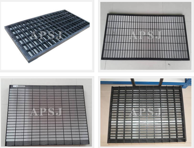
Swaco Shaker Screen
Swaco shaker screen models: Swaco mongoose/meerkatpt shaker screen, Swaco MD-2/MD-3 Shaker screen, Swaco Mamut Shaker Screen,Swaco ALS II Shaker Screen, Swaco BEM-3 Shaker Screen.
Swaco Shaker Screen types also includings steel frame shaker screen and composite frame shaker screen.
1). Steel frame shaker screen main feature as follows:
-
These products screen panels are constructed with two or three 304 or 316 stainless steel wire cloth layers with s steel backing plate and steel frame combined together. Because of different mesh size and hole size, get an better filtering effect.
-
The bottom high strength steel frame, supporting bar with the moderate tension screen cloth, combined together, infinitely enhance the screen intensity and endurance, get an better filtering effective. Mesh sizes ranging from 20to 325. The whole cloth is divided into independent small surfaces, prevent the part excessive expansion damaged, with a special rubber plug together to repair damage, can save the time to replace the screen, Increase the efficiency and reduce the cost.


2) Compoiste Frame Shaker Screen is made by polyurethane material frame with two or three layers 304 or 316 Stainless steel wire cloth, Main feature as follows.
-
High strength plastic frame and moderate tension screen cloth that from a reliable whole, greatly enhance the tolerable.
-
The screen is divided into several independent small cloths to pervent excessive expansion of local damage.At the same time, With a special rubber plug to repair damage, it can save time and reduce use-cost.
-
Rapid wedge tensioning devices make screen installation more convenient, and save the time of machine half for changing.
-
Excellent polyurethane material frame enhance corrosion resistance, have a good stock absorption and ectend working life of screen
Swaco Shaker Screen
Swaco Shaker Screen,Swaco Oil Shale Shaker Screen,Swaco Shale Shaker Screen,Swaco Oil Shaker Screen
Anping Shengjia Hardware Mesh Co.,ltd , https://www.oilshakerscreen.com