According to the distribution of solid particles in the slurry on the cross section of the tube and the groove, the slurry can be divided into two types of fluids: homogeneous and heterogeneous. The so-called "homogeneous fluid" means that there is no obvious solid concentration gradient between the upper and lower layers in the cross section of the tube and the groove; the suspended solids in the slurry have no inertial force tending to settle downward; the viscous force plays a leading role among the particles. The heterogeneous fluid is just the opposite. The change of the solid concentration in the upper and lower layers is very obvious; the suspended solid particles are strongly affected by the inertial force, and the viscous force is almost non-existent. In short, the homogenization flow is a slurry with a very high viscosity; the non-homogeneous flow is dominated by the influence of solid particle inertia, so that the viscous force is negligible. Strictly speaking, the true homogeneous fluid is objectively rare, because the suspended solids that are absolutely stationary in the slurry do not exist, there is always a tendency to sink, but some fine solid particles sink very slowly. Only. Therefore, there is only an approximately homogeneous fluid objectively. It is generally referred to as a "quasi-homogeneous" (pseudo-homogeneous, homogeneous) fluid. At present, the so-called "high-concentration slurry" for pipeline transportation mainly refers to such a slurry.
For a solid-liquid two-phase flow slurry, it is basically in the form of rolling, jumping, suspension, and layer shifting. When the solid content in the slurry is high, especially a certain amount is less than 0.01. In the case of fine particles of millimeters, there will be no separation or significant sorting of solid or liquid phase even under static conditions. At this point the water flow essentially belongs to a quasi-homogeneous fluid of one phase. This quasi-homogeneous fluid may be a Newtonian fluid, but more are non-Newtonian fluids.
When the clean water and heterogeneous fluid flow in a layered manner in the pipeline, the relationship between the stress caused by the shearing action and the shear rate is proportional, that is, the following Newton's law formula is met:

The above formula is specific to the fluid between the plates. For the pipe flow, the above formula should be rewritten as the Hagen-Poiseuille formula.
 [next]
The fluid obeying the above two formulas is called the Newtonian (type flow) body. If formula (1) is plotted as a graph, the relationship between the shear stress and the shear rate of the laminar flow state is a straight line passing through the origin of the coordinate (bottom), and the slope of the straight line is the viscosity. It is clear that such fluids can be characterized by a flow parameter, viscosity (viscosity factor), during laminar flow.
Most homogeneous fluids are not subject to Newton's law, so they are not Newtonian. The suspended solid particles in such a fluid are substantially uniformly distributed and can be considered as a single-phase fluid. At laminar flow, the shear force (ie, shear stress) at any point within the fluid is only a function of the shear rate at that point, independent of other locations of the fluid, other factors, and the like. The relationship between shear force and shear rate is not a straight line passing through the origin, or it is not a straight line at all (in the figure). Therefore, it does not conform to the characteristics of formula (1), so this type of fluid is called "non-Newtonian". fluid". Such fluids include many types, such as pseudoplastic, Bingham behavior, yield-pseudoplastic, and the like. However, the metal slurry, the mostly purely viscous non-Newtonian fluid flow Bingham. Its main feature is that this fluid has a three-dimensional structure with sufficient stiffness at rest, sufficient to resist any force less than the yield stress. When the yield stress is exceeded, the structure is decomposed and exhibits the same characteristics as Newtonian fluid. However, when the force is reduced below the yield stress, the original structure is restored. The formula representing the Bingham type property is:

In order to apply to the tube flow, Bucking Ham converts the formula (3) into the following equation, namely the Bukingham Equation.
 [next]
Fluids conforming to equations (3) and (4) are referred to as non-Newtonian Bingham type fluids. The high concentration of metal ore and tailings slurry have the characteristics of this type or similar to this type of fluid. This property of the slurry is often referred to as "rheological properties" or "rheological properties."

In order to reduce energy consumption and head loss during slurry transport, it is generally desirable to limit the delivery flow rate to a viscous transitional flow rate region where laminar flow is converted to turbulent flow, where the flow rate is generally referred to as the "critical flow rate." Its main feature is that viscosity has a significant impact on head loss. Therefore, in the design of slurry tube and tank transportation, it is necessary to determine the flow pattern (rheological characteristics) of the slurry, the relationship between flow pattern and viscosity coefficient, critical flow rate, head loss and other conditions and data. However, in rheology, the expressions describing the relationship between flow pattern and viscosity coefficient have not been widely applied. Therefore, the required data and data can only be obtained by means of experimental means or semi-test semi-trial calculation. These data and data are related to the characteristics of suspended media and solid materials. In particular, the density, particle size of the solid particles, the content of the solid material in the slurry (slurry concentration), and the pipe diameter are the main factors that determine the properties of the pulp and the transport parameters. At the same time, there is a relationship between them that interacts with each other. For example, changes in the particle size composition of the solid will have a great influence on the viscosity of the slurry. The finer the particle size or the more uniform the particle size composition, the greater the viscosity, which limits the increase in transport concentration. At the same time, it will cause an increase in conveying resistance. Therefore, under a certain upper limit particle size condition, appropriately increasing the coarse particle content in the slurry will be beneficial to reduce the relative viscosity and transport resistance of the same slurry concentration. However, the amount of increase should not be too large or the particle size is too large, and when the limit is exceeded, the flow pattern of the slurry will be changed. Tests have shown that various slurries (such as concentrates, tailings pulp) will have a particle size composition that minimizes the relative viscosity within a certain upper particle size range, and this particle size composition is capable of separating particles in the slurry. The ultimate volume concentration "Cvm" reached is the mark. That is, the solid particles have the highest solidity and the relative viscosity is the smallest. In addition, the slurry transport stability also has certain requirements on the particle size composition. It is generally considered that particles with a particle size composition of less than 0.074 mm account for at least 50% of the particles to have sufficient stability, so that the transport system works safely and reliably. The main function of the fine particle material is that it can form a suspension carrier with the liquid medium, and this carrier will support the coarse particles to suspend. Therefore, high content of fine particles in the slurry will be advantageous for transportation. At present, in some examples of concentrate transportation of metal mines abroad, particles smaller than 0.074 mm account for more than 90% of the solid content in the slurry. However, as already mentioned, the greater the viscosity of the slurry, the greater the viscosity of the slurry. At the same time, it is difficult to dewater the material at the end of the transport, so it is necessary to contain a certain amount of coarse particles which can be suspended in the suspension carrier in the fine particles to facilitate the transport. The upper particle diameter of such coarse particles of the metal concentrate is about 0.0208 to 0.147 mm (65 mesh to 100 mesh) from the currently known production examples, and the amount of such coarse particles generally mixed into the suspension carrier. It is generally 10% or less of the total solids.
It can be seen that the rationality of the composition of the slurry particles has a significant influence on the fluidity (viscosity, resistance) and stability of the slurry (whether the particles are easily separated and precipitated, the conveying flow rate, etc.), and it is also related to the system. The effect of pulp and dewatering, and the composition of the particles and the concentration of the slurry have a mutually restrictive relationship. Therefore, the selection of the optimum particle size composition and the optimum transport concentration (ie the best solid particle content in the slurry) is the pipeline hydraulic transport test. The main problem solved.
The product produced by the mineral processing technology--fine pulp can not meet the requirements of pipeline hydraulic transportation. Therefore, it is often necessary to carry out the processing to adjust the particle size grading, conveying concentration and pH value before transportation. - Pre-processing. Through the pre-treatment, the slurry can reach the near-ideal optimal state suitable for transportation, which plays a good role in reducing the transportation energy consumption, improving the service life of the conveying system and ensuring safe production. However, this will inevitably increase the production process, and the filtration dewatering of the slurry at the end of the delivery may also cause some trouble. Therefore, in the design of the slurry pipeline transportation system, it is necessary to seriously carry out technical and economic considerations, weigh the advantages and disadvantages, and determine a reasonable transportation plan.
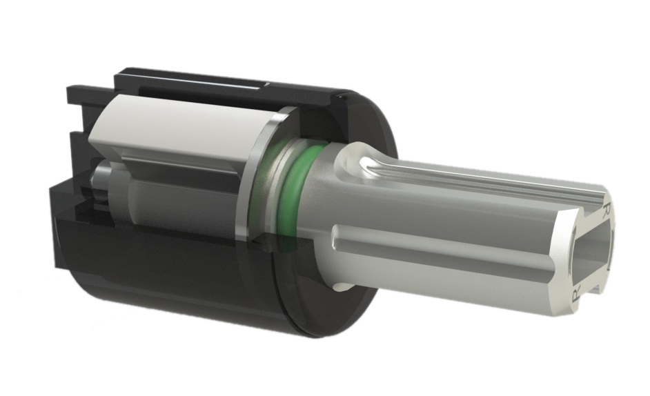
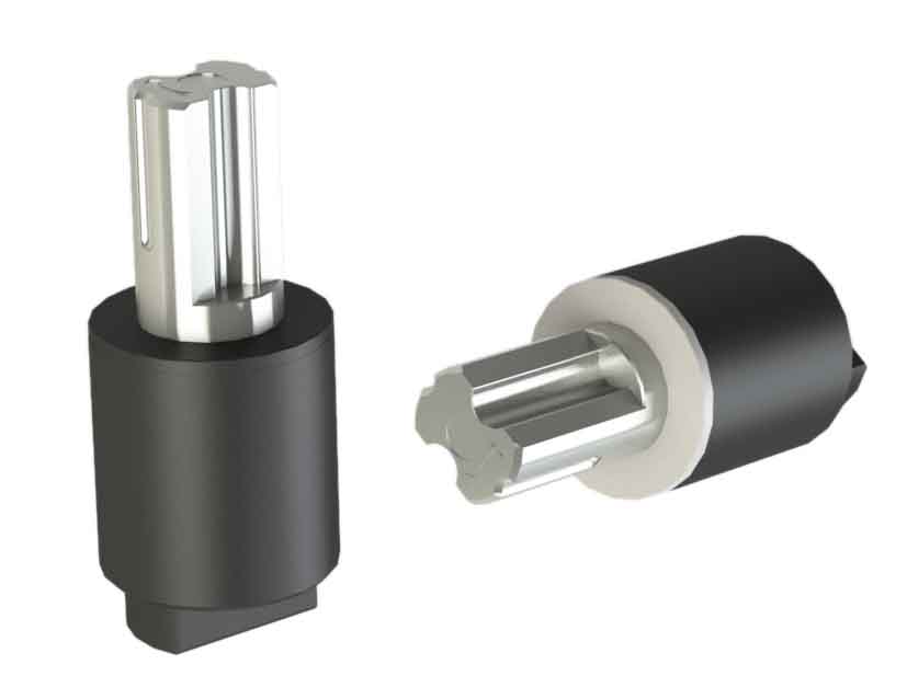
Rotary Damper is mainly aimed at damping control of the motion of some parts in the direction of rotation, ensure that the rotary motion is achieved in soft, silent and safe environment. Rotary damper according to the rotation angle, rotary damper can be divided into more than 360 degrees circular rotation angle and limit rotation angle. Different types according to the installation type of the product, rotary damper can be divided into Barrel Damper, Vane Damper, stop damper, Gear Damper , Disk Damper and Shaft Damper etc. ABD rotary dampers are used to dampen drives, control speed, and many other applications.
Our rotary dampers are widely used in automobile interior decoration, household electric appliances, furniture, invisible screens, theater seats and bathroom products, etc. ABD damper is conducive to performing structural movement in soft, silent and safe environment, mitigating impact load, avoiding strike damage, prolonging mechanical life, reducing noise disturbance, improving product quality and improve customer satisfaction.


Full inspection of all our products torque , guarantee the stability of the product torque. The company's salesmen after years of working in the market, ensuring the timeliness of feedback and customer service. Our company has a leading R & D team in the peer, our product has several patents, ensuring a steady stream of new product development for the company. At present, our company developed products are the first to peer object of imitation.
If you have any questions, please contact with us directly and we have the perfect after-sales service and technical support. We look forward to working with you side by side, to be a long-term partner whom you can trust.
Rotary Damper
Rotary Damper,Friction Rotary Dampers,Small Rotary Dampers,Large Rotary Dampers
Shenzhen ABD Equipment Co., Ltd. , https://www.abddamper.com