In the high-definition network video surveillance system, there are often friends who feedback the picture delay and the phenomenon of the card, etc. There are many reasons for this phenomenon, but in most cases, the configuration of the switch is not reasonable enough, resulting in insufficient bandwidth.
First, choose according to the code stream and quantity of the camera
1, camera code stream
Before choosing a switch, you must first figure out how much bandwidth each image takes.
Take an example of an early IPC:
The 720P network camera has a main stream of 2~3M and a sub-stream of 0.8~1M, which is about 4M.
1080P network camera, the main stream is 4~6M, the sub-stream is 0.8~1M, a total of about 7M.
2, the number of cameras
To figure out the bandwidth capacity of the switch. Common switches have hundreds of megabytes of switches and gigabit switches. Their actual bandwidth is generally only 60 to 70% of the theoretical value, so the available bandwidth of their ports is roughly 60Mbps or 600Mbps.
In terms of network topology, a local area network is usually two to three layers. The end of the camera is the access layer. Generally, a 100M switch is enough, unless you have a lot of cameras connected to a switch.
The aggregation layer and the core layer are calculated according to how many road images are gathered by the switch.
The calculation method is as follows: if a 720P network camera is connected, generally 15 channels of images are used, and a 100-megabit switch is used; if more than 15 channels are used, a Gigabit switch is used; if a 1080P network camera is connected, generally 8 channels of images are used, and a 100-megabit switch is used. Eight channels use Gigabit switches.
Second, the choice of the switch
With the increasing use of high-definition cameras, how to choose the appropriate switch that satisfies the overall network architecture performance has become an important role in the pre-planning and project quotation of HD monitoring systems. A suitable switch can not only play the role of the monitoring network but also effectively reduce the waste of resources.
The monitoring network has three layers of architecture: core layer, aggregation layer, and access layer.
Example
Take the 720P camera and PoE power supply as an example, select the corresponding switch, and connect the 720P to the first access layer switch every 20 channels.
1. Selection of access layer switches
Condition 1: Camera flow: 4Mbps, 20 cameras are 20*4=80Mbps.
That is to say, the access port of the access layer switch must meet the transmission rate requirement of 80 Mbps/s. Considering the actual transmission rate of the switch (usually 50% of the nominal value and 50 M of 100M), the access layer The switch should use a switch with a 1000M upload port.
Condition 2: The bandwidth of the backplane of the switch. If you select a 24-port switch with two 1000M ports and a total of 26 ports, the bandwidth requirement of the switch backplane of the access layer is: (24*100M*2+1000*2*2) ) / 1000 = 8.8 Gbps backplane bandwidth.
Condition 3: Packet forwarding rate: The packet forwarding rate of a 1000M interface is 1.488Mpps/s, and the switching rate of the access layer is: (24*100M/1000M+2)*1.488=6.55Mpps.
The switches that meet the conditions 2 and 3 are usually called line-speed switches. For example, the Fengrunda PS1024 or PS3024 can meet the line-speed switching capability, and it is also a suitable access PoE switch in this case.
According to the above conditions: When there are 20 720P cameras connected to a switch, the switch must have at least one 1000M upload port and more than 20 100M access ports to meet the demand.
2, the choice of aggregation layer switch
In the above example, if there are 5 Fengrunda PS1024 accesses in total, then the traffic of the aggregation layer is: 80 Mbps *5=400 Mbps, then the upload port of the aggregation layer must be 1000M or more.
If five IPCs are connected to one switch, an 8-port switch is generally required. Does the 8-port switch meet the requirements? Can look at the following three aspects:
Backplane bandwidth: Port number* Port speed*2=Backplane bandwidth, ie 8*100*2=1.6Gbps.
Packet exchange rate: port number * port speed / 1000 * 1.488 Mpps = packet exchange rate, that is, 8 * 100 / 1000 * 1.488 = 1.20 Mpps. The packet exchange rate of some switches is sometimes calculated to be unable to meet this requirement. Therefore, it is a non-wire-speed switch, which is prone to delay when performing large-capacity throughput.
Cascading port bandwidth: IPC code stream * number = minimum bandwidth of the upload port, that is, 4.*5=20Mbps. Normally, when the IPC bandwidth exceeds 45Mbps, it is recommended to use a 1000M expansion port.
Third, how to choose a switch?
Example
There is a campus network, more than 500 high-definition cameras, and the code stream is 3~4 megabytes. The network structure is divided into the core layer of the access layer convergence layer. Stored in the aggregation layer, each aggregation layer corresponds to 170 cameras.
The problem: how to choose the product, the difference between 100 Mbps and Gigabit, what are the reasons for the image transmission in the network, and what factors are related to the switch...
1, backplane bandwidth
The sum of all port capacity x port numbers should be less than the nominal backplane bandwidth, enabling full-duplex non-blocking wire-speed switching, proving that the switch has the conditions for maximum data exchange performance.
For example, a switch with up to 48 Gigabit ports should have a full configuration capacity of 48 × 1G × 2 = 96Gbps to ensure non-blocking wire-speed packet switching when all ports are in full duplex. .
2, packet forwarding rate
Full configuration packet forwarding rate (Mbps) = full configuration GE port number × 1.488 Mpps + full configuration 100 Mbps port number × 0.1488 Mpps, of which 1 gigabit port has a theoretical throughput of 1.488 Mpps when the packet length is 64 bytes.
For example, if a switch can provide up to 24 Gigabit ports and the claimed packet forwarding rate is less than 35.71 Mpps (24 x 1.488 Mpps = 35.71), then there is reason to believe that the switch uses a blocking structure design.
Generally, a switch with a backplane bandwidth and a packet forwarding rate is a suitable switch.
A switch with a relatively large backplane and relatively small throughput, in addition to retaining the ability to upgrade and expand, is a problem in software efficiency/special chip circuit design; a switch with a relatively small backplane and relatively large throughput has a relatively high overall performance.
The camera stream affects the resolution, usually the stream setting of the video transmission (including the encoding and decoding capabilities of the encoding transmitting and receiving devices, etc.), which is the performance of the front-end camera, independent of the network.
Usually, users think that the definition is not high, and the idea that is caused by the network is actually a misunderstanding.
According to the above case, calculate:
Code stream: 4Mbps
Access: 24*4=96Mbps<1000Mbps<4435.2Mbps
Convergence: 170*4=680Mbps<1000Mbps<4435.2Mbps
3. Access switch
The link bandwidth between access and aggregation is mainly considered, that is, the uplink link capacity of the switch needs to be larger than the number of cameras * code rate accommodated at the same time.
In this way, video real-time recording is no problem, but if a user sees the video in real time, it needs to consider this bandwidth. The bandwidth occupied by each user to view a video is 4M, if each camera of an access switch is If one is watching, you need the camera's *code rate*(1+N) bandwidth, which is 24*4*(1+1)=128M.
4, aggregation switch
The aggregation layer needs to process the 34M code stream of 170 cameras (170* 4M=680M) at the same time, which means that the aggregation layer switch needs to support the forwarding capacity of 680M or more at the same time. Generally, the storage is connected to the aggregation, so the video recording is wire-speed forwarding.
However, considering the bandwidth of real-time monitoring, each connection occupies 4M, and a 1000M link can support 250 cameras to be debugged. Each access switch is connected to 24 cameras, 250/24, which is equivalent to the network can withstand the pressure of real-time viewing of 10 cameras per user at the same time.
5, the core switch
The core switch needs to consider the switching capacity and the link bandwidth to the aggregation. Because the storage is placed at the aggregation layer, the core switch does not have the pressure of video recording, that is, just consider how many people watch video at the same time.
Assume that in this case, there are 10 people watching at the same time, each person watching 16 channels of video, that is, the exchange capacity needs to be greater than 10*16*4=640M.
6, switch selection focus
When video surveillance in the LAN is selected for the switch, the choice of the access layer and the aggregation layer switch usually only needs to consider the factor of the switching capacity, because the user usually connects and acquires the video through the core switch.
In addition, since the main pressure is at the aggregation layer switch, it is very important to select the applicable aggregation switch because it has to bear the monitoring of the stored traffic and the pressure to view the monitoring in real time.
For the access switch, there is no essential difference between the port of the lower port and the port of the camera, but the uplink must be gigabit.
Fe-Gr-Al fiber sintered felt filter media
Describe:
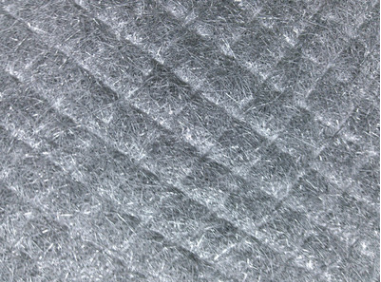
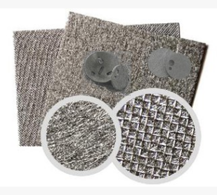
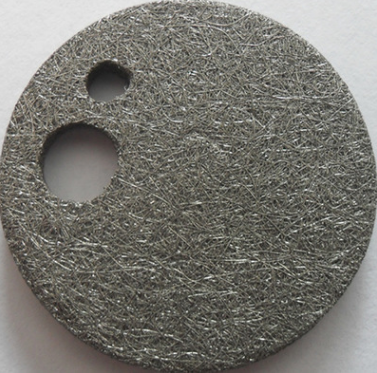
The Filter Material of iron-chromium-aluminum dust filter tube is made from iron chromium aluminum fiber through opening and loosening machine, then made into cotton by special technology, and then sintered by vacuum sintering furnace. Because of its deep labyrinth structure, the filtration effect is much better..
Fe-Cr-Al fiber sintered felt is a kind of metal fiber sintered felt with long service life, environmental protection and energy saving, high temperature resistance, resistance to deformation, no carbon deposition, foldable, good toughness and uniform pore size distribution. It is widely used in automobile tail gas treatment, burner, boiler retrofit, gas conditioning, glass annealing, food baking, oven, heater, paper painting, drying and so on.
Characteristics:
1. High temperature resistance 1200 degrees.
2. Strong cold and thermal shock ability.
3. No water absorption.
4. Thermal inert extremely small.
5. Combustion complete radiation .
6. Long service life.
Applications:
Fe-Cr-Al fiber sintered felt is widely used as filter material in chemical and European standard diesel vehicle exhaust emission equipment. Fe-cr-ai alloy porous body position three-dimensional junction network structure. The pore size is 0.1 mm and the porosity is up to85%, it is the best choice for monolithic catalyst support material.


Special Metal Filter Materials
Perforated Sheet,Special Metal Filter Materials,Special Material Filter,Perforated Sheet With Sintered Mesh
Henan Sinofiltec Technology Co.,Ltd , https://www.airfilters.pl


