Domestic high-rise buildings are constantly being built, with high heights, numerous floors, and large volumes, and the resulting internal construction equipment is also large. In order to improve equipment utilization, use energy reasonably, and strengthen monitoring of the state of construction equipment, a building automation control system is naturally proposed.
The building automation control system automatically controls the electromechanical equipment inside the building. Software can systematically manage interrelated devices, take advantage of the overall advantages and potential of the device, improve equipment utilization, optimize equipment operation status and time (but does not affect the ergonomics of the equipment), thereby extending the service life of the equipment and reducing Energy consumption, reducing the labor intensity and working hours of maintenance personnel, and ultimately reducing the operating costs of equipment.
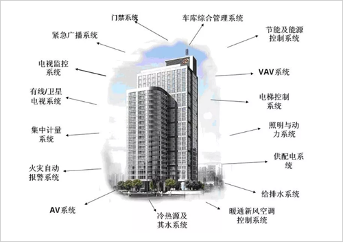
The building automation system consists of the following components:
(1) Monitoring of operation and management of construction equipment, including: HVAC monitoring; drainage system monitoring; supply and exhaust system monitoring; power supply and lighting system monitoring; elevator operation monitoring; cold and heat source system Monitoring.
(2) Fire alarm and fire control linkage control, elevator operation control.
(3) Public safety technical prevention, including: video surveillance system; anti-theft alarm system; entrance and exit control and access control system; security personnel inspection system; vehicle warehouse integrated management system; various important warehouse prevention facilities;
Many electromechanical devices have inherent interconnections, so perfect automation management is required. Establish an electromechanical equipment management system to achieve integrated management, scheduling, monitoring, operation and control of electromechanical equipment.
1. Management purposes
Automatic control, monitoring, and measurement are the three major elements of construction equipment management. The purpose is to correctly grasp the operational status, accident status, energy consumption, and load changes of construction equipment. Especially after using the electronic computer, it can save manpower and save energy. It is generally believed that energy can be saved by 25%.
According to the Technical Report of the Institute of Electrical Engineering of Japan, the effect of using an electronic computer management system can be reduced by about 30% compared to the effect of not using it. The energy saving mentioned here is the energy saving method adopted in the high utilization rate of the necessary energy. The methods used in this operation control mainly include: effective operation of the machine; changing the indoor temperature and humidity conditions; controlling the illuminance; controlling the operation time of the equipment to a minimum; reducing the amount of outdoor air taken. The electrical consumption rate in a building accounts for 70% to 90% of the total energy consumption. Therefore, energy conservation should start with electrical aspects and reduce the consumption of electrical energy.
2, management object
The management objects of construction equipment are mainly electrical equipment, air conditioning equipment, and sanitary equipment.
(l) Electrical equipment: The management electrical equipment mainly monitors the operating state, measuring points and protection devices of the machine. The main object of management is the state monitoring of circuit breakers, transformers, contactors, fuses, capacitors, etc. of each power distribution system. Measurements are primarily measurements of current, voltage, active power, reactive power, and power factor of the power system.
(2) Air-conditioning equipment: Manage air-conditioning equipment to monitor the status of the freezer, air conditioner, water pump, etc.; measure the temperature and humidity, and adjust the temperature and flow of the cold and heat source required for the air-conditioning system.
(3) Sanitary equipment
3, control function
The building's automatic control of the building's equipment is centered on air conditioning control. The automatic control of the air conditioning system is an automatic adjustment of the general thermodynamic process. The automatic adjustment of the air conditioning system has the following advantages:
(1) For production buildings, the control accuracy of temperature and humidity can be improved, and the quality of products can be improved. The residential and commercial buildings are mainly to improve people's comfort.
(2) The energy (hot or cold) can be increased or decreased according to the situation where the volume is changed, so energy consumption can be reduced and energy can be saved.
(3) It can reduce the labor intensity.
4, automatic adjustment of air conditioning units
The control system adopts DDC control. The temperature detected by the temperature sensor installed in the return air pipe is sent to the DDC controller to compare with the set point temperature. The proportional integral plus differential control is used to output the corresponding voltage signal, and the control is installed in the return pipe. The action of the upper electric control valve keeps the return air temperature within the required range.
The humidity detected by the humidity sensor installed in the air supply pipe is sent to the DDC controller for comparison with the set point humidity. The proportional integral control is used to output the corresponding voltage signal, and the action of the electric steam valve is controlled to keep the air supply humidity at the place. The range needed.
The temperature/humidity detected by the temperature and humidity sensors installed in the return air duct and the fresh air duct is sent to the DDC controller for return air and fresh air enthalpy calculation, and the corresponding voltage signal is output according to the ratio of return air and fresh air enthalpy. Control the proportional opening of the return air damper and the fresh air damper to make the system energy-saving.
(1) All the test data in the system can be displayed on the display, such as: fresh air, return air, temperature and humidity of the air supply, filter silencing alarm, fan opening and closing status.
(2) Through the pre-written logic program in the DDC controller, the system can perform the following chain functions: the damper installed at the entrance of the fresh air is interlocked with the fan. When the fan stops, the fresh air damper is fully closed; the electric control valve is interlocked with the fan. When the fan stops, the electric control valve is also closed at the same time; the start and stop state of the fan is detected by the differential pressure switch. When the fan starts, when the differential pressure on both sides of the fan exceeds its set value, the normally open contact in the differential pressure switch is closed, the signal is sent to the DDC controller, and the control program of the system is put into operation immediately.
(3) The portable detector can be used to extract and modify any data in the DDC digital controller, such as sensor detection range and control program parameters, including input to output.
(4) Connected to the network controller through the serial interface of the DDC, which becomes the most basic monitoring unit of the central monitoring system.
5, central station monitoring function
Using Windows NT as the operating platform, using industry-standard application software, distributed control system, and secondary network structure, the graphical operation interface of the whole culture monitors the operation status of the whole system, and provides on-site pictures and process flow charts (such as air conditioning control system). Figure), real-time graph, monitoring point table, drawing plane layout, display the operation of the device in a visual and intuitive dynamic graphic mode. Draw a plan or flow chart and embed dynamic data to display the status of each monitoring point in the figure, and provide operational instructions to modify parameters or issue instructions.
There are several ways to view the device status, such as through a floor plan or flow chart, through the pull-down menu or function keys for common function manipulation, click the mouse to view the device status and related parameters in detail.
6, control function
The field device can be manually controlled by the operation of the graphic on the central station, such as the ON/OFF control of the device; the operation mode can be set by selecting the operation, such as selecting the manual manual mode or the automatic operation mode; The menu allows easy modification of process parameters.
The operating authority of the system is strictly managed to ensure the safe operation of the system. The identification and control of the identity of the operator in the form of a password. Operators can be divided into 5-10 security management levels from low to high depending on their identity. Advanced alarm function: When the system fails or the equipment on the site fails and the monitored parameters exceed the limit, an alarm signal is generated. The alarm signal always appears at the bottom of the display, which is the sound and light alarm. The operator must confirm the alarm signal. Released, but all alarms will be recorded in the alarm summary table for the operator to view. The alarm is divided into 4 priority levels.
7, integrated management functions
Establish a historical file database for data that has research and analytical value and should be preserved for a long time. Use the popular common standard relational database software package and hard disk as a large-capacity memory to build a database and form display or print functions such as graphs.
Provide summary report: as system operation status monitoring, management level evaluation, further optimization of operation parameters and as the basis for equipment management automation, such as using summary report, record daily, weekly, monthly energy consumption and its accumulated value, Provide a basis for saving energy use; and such as equipment running time, start and stop times summary report (different devices are listed separately), to provide basis for equipment management and maintenance.
A graphical time program plan can be provided to schedule a building equipment operation schedule. Schedules are available by week, by region and by calendar and holiday.
Perforated stainless steel grating Polymer Drainage Channel
Products description
1. The U type drainage channel can fixed with ductile iron,stainless steel ,hot galvanized steel and stamping
gratings . With the drain plug,outfall together constitute a complete drainage system .
The drainage channels have many specification ,can make according to your requirement .Widely use
on the gound drainage system of national defense construction, civil building, commerce,industrial.
For example : airport ,port,park, stadium,many kinds of lanes,square drainage,street drainage and so on .
2. The material for our drainage is stainless steel , galvanized steel and cast iron

Middle slot liner drainage channel and side slot liner drainage channel

Application
polymer resin concrete drainage substitute for cement concrete is widely used in below areas:
Building entrances/Service stations/Car parks/Pedestrian precincts/Kerbside drainage/Industrial Ports/Train Stations


Polymer Concrete Drainage Channel
Polymer Concrete Drainage Channel,Drainage Channel,Polymer Concrete Precast Drainage Channel,Polymer Concrete Drainage Linear Channel
Hebei Mingda International Trading Co.,Ltd , https://www.amazingcastings.com