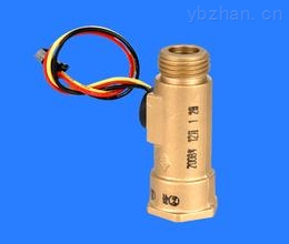
The water flow sensor is mainly composed of a copper valve body, a water flow rotor assembly, a steady flow component, and a Hall element . It is installed at the water inlet of the water heater to measure the flow of incoming water. As water flows through the rotor assembly, the magnetic rotor rotates and the rotational speed changes linearly with flow. The Hall element outputs a corresponding pulse signal to the controller. The controller judges the flow rate of the water and regulates the current of the proportional valve so that the gas volume can be controlled through the proportional valve to prevent the phenomenon of summer warm and cold during the use of the gas water heater . .
The water flow sensor fundamentally solves the disadvantages of the high water pressure of the differential pressure type water and gas linkage valve and the proneness of the flap water valve to malfunction. It has the advantages of being sensitive, long life, quick action, safe and reliable, convenient connection and low flow rate (1.5L/min). It is well received by users.
The water flow rotor assembly is mainly composed of a turbine switch housing, a magnetic rotor, and a brake ring. When the water flow switch mode is used, the performance is better than that of the mechanical differential pressure disk structure, and the size is significantly reduced. When the water flows through the turbine switch case, the magnetic rotor is driven to rotate, and when the different magnetic poles are close to the Hall element, the Hall element is turned on, and the time when it is off. The element is disconnected. As a result, the rotor speed can be measured. According to the curve of measured water flow, rotor speed and output signal (voltage), the starting water pressure of the water heater can be determined, and the starting water flow corresponding to the starting water pressure and the starting rotation speed of the rotor can be determined. By the control circuit, the water heater can be started when the rotor speed is greater than the start speed; the water heater stops working when the speed is less than the start speed. This water heater start pressure is generally set at 0.01MPa, starting water flow rate of 3 ~ 5L/min (to meet the water heater standards for the maximum temperature rise limit). In addition, as the water is cut by the magnetic field of the permanent magnetic material and becomes magnetized water, the amount of oxygen in the water increases, so that the person feels refreshed after bathing. The function of the brake ring is to stop the rotation of the magnetic rotor rotating at a high speed and stop the pulse signal output. The controller does not receive the pulse signal and immediately controls the gas proportional valve to close the valve, cut off the air supply and prevent dry burning.
The water flow sensor uses the Hall effect of the Hall element to measure magnetic quantities. The positive electrode of the Hall element is serially connected to a load resistor, and a 5 V DC voltage is applied to the same, so that the direction of the current is orthogonal to the direction of the magnetic field. When the water pushes the magnetic rotor through the turbine switch case, a rotating magnetic field of different magnetic poles is generated, and the magnetic induction lines are cut to generate high and low pulse levels. Since the frequency of the output pulse signal of the turbine flow meter is proportional to the rotation speed of the magnetic rotor, the rotation speed of the rotor is proportional to the water flow, and the gas water heater is started according to the size of the water flow.
The feedback signal of the water flow sensor judges the value of the water flow through the controller. According to the different types of gas water heaters, the best starting flow rate can be selected to achieve ultra-low pressure (below 0.02 MPa) start-up.
First, the accuracy level. The accuracy level of the water flow sensor is usually relatively high. In general, the higher the accuracy is, the more sensitive the operating environment of the site is. From the economic benefits above, do not blindly seek a high level of accuracy. In the case of large-diameter flow, high-precision sensors should be selected for the West-East Gas Pipeline project, and normal turbine flow sensors can be selected for applications where the amount of transport is small and measurement is required.
Second, density. The stability of the density has a great influence on the measurement accuracy of the water flow sensor. With respect to occasions where the density is often changed, it is also necessary to adopt a correction method for the flow coefficient, especially regarding the low flow area.
Third, the scale of traffic. The selection of water flow sensor flow size directly affects its accuracy and years of use. It also determines the choice of flow sensor caliber. The selected flow rate is usually based on the following principle: the minimum flow rate should be greater than or equal to the minimum flow rate that can be measured by the exterior, and the maximum flow rate should be less than or equal to the maximum flow rate that can be measured by the exterior; the maximum flow rate should be the maximum flow rate when the uninterrupted operation is less than eight hours. About 1.3 times of the time; on the occasion of uninterrupted operation beyond eight hours, the maximum flow rate should be more than 1.4 times the maximum flow of practice; the minimum flow rate should be 0.8 times the minimum flow rate is the best.
Fourth, the pressure is lost. The smaller the pressure loss, the smaller the energy consumption of the gas during the activity, which can save energy, reduce transportation costs, and improve utilization. Therefore, at the time of selection, try to select a small turbine flow sensor with little pressure loss. In general, the turbine flow sensor using the semi-ellipsoidal front deflector has less pressure loss than the turbine flow sensor of the cone's front deflector.
Fifth, the layout method. The layout method uses the above three methods to determine: the best choice for the internal layout of the reverse push turbine flow sensor, due to the layout in a certain flow rate can make the impeller in a floating condition, there is no axial contact point, no end surface conflict and wear, Extend the service life of the bearing. With regard to the flow sensor of the horizontal layout device, the connection method to the pipeline can be the Flange connection, the thread connection, and the clamping connection. The flow sensor for the straight layout device can only be used for the threaded connection. [1]
The disadvantage of the differential pressure type water and gas linkage valve is that the starting water pressure is high, and in order to reduce the starting water pressure, it is necessary to sacrifice a certain steady flow characteristic (flow stabilization capability when the water pressure fluctuates).
In order to achieve the balance between the two, the diaphragm of the water valve can only be increased, but the cost will increase with the increase of the valve body, and the flow starting pressure index cannot be too low. For water flow sensors, increase the steady flow components at the water outlet and use steady flow. The geometric dimensions and physical properties of the ring have successfully developed a steady flow component for water heaters of different capacities through tests, with good steady flow characteristics (When the inlet water pressure changes from 0.1 to 0.5 MPa, the water output changes at 3 L/min. Within), to ensure that the water pressure changes, keep the flow within a certain range, to achieve a constant temperature effect.
Comparing differential pressure water and gas linkage valves and water flow sensors, it can be seen that the former is mechanical, the structure is more complex, and the volume is larger, but the control circuit is simple; the latter is electrical, the structure is relatively simple, and the volume is small, but the control circuit complex. More importantly, the former has a higher initial hydraulic pressure and a greater resistance to the waterway system. It should not be used in large-capacity water heaters AZ above 10L/min; while the latter has low starting water pressure, and the water system resistance is small. Large capacity above 10L/min. Water heater has been widely used.
Water flow sensors are more useful and intuitive to use in more accurate water control systems. Take a pulsed signal output water flow sensor as an example. In the IC water meter and flow control requires a higher hydropower heating environment, the water flow sensor has a stronger advantage. Together with the convenience of PLC control, the linear output signal of the water flow sensor can be directly connected to the PLC, or even corrected and compensated, and can be used for quantitative control and electrical switching. Therefore, the use of a water flow sensor with a relatively higher water control system gradually replaces the flow switch and has the sensing function of the water flow switch. This also satisfies the need for water flow measurement.
Water flow sensor in the use of matters needing attention
1. When magnetic data or data on the magnetic force of the sensor is close to the sensor, its characteristics can be changed.
2. In order to prevent particles and impurities from entering the sensor, it is necessary to install a filter at the inlet of the sensor. 3, the device of the water flow sensor should avoid a strong sensation and shaking environment, to prevent affecting the sensor's measurement accuracy. [2]
Reference editing area
RSS VALVE'S Rubber Expansion Joint, pressure rating: PN10, PN16, PN25, Class125, Class150; Expansion Joint's Flange material: carbon steel A105N flange or ductile iron flange; Expansion Joint Body material EPDM NBR or Nature rubber body; Size from DN50 to DN2000 (2" to 80"); Feature: easy installation, maintenance free
Flange Expansion Joint, Rubber EPDM NBR, Nature Rubber, Expansion, PN16 PN10 Class150, Ductile Iron Flange
SUZHOU RSF VALVE CO.,LTD , https://www.rsf-valve.com